Façade cassettesfree
Ridge cassette
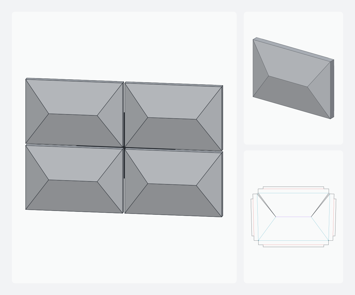
Raised horizontal ridge: two trapezoidal slopes and two triangular hips. Ridge length, position and offset are adjustable; full width possible.
Open in the studio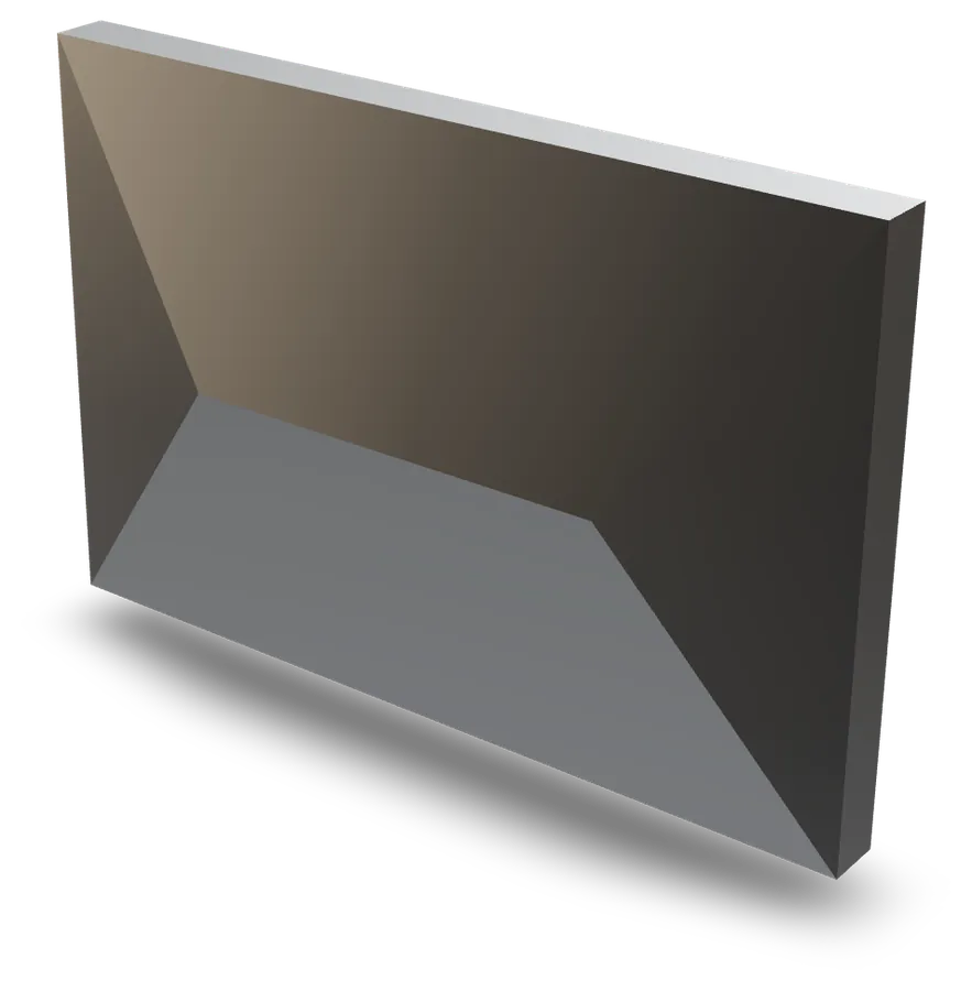
ACM 3D Studio
- Developed
- 723.9 × 512.9 mm
- Material
- ACM 4 mm
- Folds
- 11
- Mark
- ridge
Fabrication data
Ridge cassette — at 600 × 400 mm in 4 mm ACM, this family unfolds into a 723.9 × 512.9 mm flat pattern with 11 folds, all grooved from the back: no pass on the coated face. A 1,500 × 3,200 mm sheet holds 12 of them, for 13.9 % waste.
- Material per panel
- 0.344 m²
- Folds
- 11
- Total groove length
- 4,464 mm
- Cutting length
- 3,963 mm
- Corner slits
- 2
- Corner reliefs
- 2
V-grooves (apex angle)
- 90°1,664 mm
- 78.7°1,197 mm
- 75.1°797 mm
- 18.7°506 mm
- 22.6°300 mm
Panels per sheet
- 1,220 × 2,440 mm6(30.6 % waste)
- 1,500 × 3,200 mm12(13.9 % waste)
DXF layers
- CONTOUR3,963 mm
- RAINURE_1001,993 mm
- RAINURE_901,664 mm
- RAINURE_160506 mm
- RAINURE_135300 mm
The names and colours your CAM software will show. RAINURE_AVANT: fold concave on the visible face, sheet flipped for that pass.
Computed by the engine at the default parameters, on 4 mm ACM and the reference router. Your own machine and material profiles change these values in the studio.
Parameters
| Parameters | Range | Default |
|---|---|---|
| Width | 200 – 3,000 mm | 600 mm |
| Height | 200 – 3,000 mm | 400 mm |
| Relief height | 5 – 150 mm | 40 mm |
| Ridge length | 10 – 100 % | 50 % |
| Ridge centre X | 10 – 90 % | 50 % |
| Ridge position Y | 10 – 90 % | 50 % |
| Return depth | 0 – 200 mm | 40 mm |
| Fixing tabs | — | ✓ |
| Tab width | 10 – 60 mm | 20 mm |
PresetsCentred ridgeShort ridgeOffset ridgeFull width
Manufacturing constraints
- The return must exceed the groove width plus half the bend deduction, or the groove eats into the return.
- Facet-to-facet folds are grooved with the smallest cutter of the profile, V left open: the angle is held by the geometry. The angle between two facets must not exceed that cutter’s apex angle.
- Vertical returns, all tabs flat in the −D plane (rail mounting). The facet-to-return fold is 90° ± slope: below 90°, the 90° cutter is left open and the return is held by the riveted tab; above 90° (facet descending towards the edge), a wider cutter (60° nominal = 120° apex) or the machine profile’s overfold tolerance is needed.
- Every raised vertex requires a V-slit to the edge (a flat sheet has 360°, the relief less). Near the vertex the slit is narrower than the contour tool: it is cut along its axis and the tool bites each facet by up to Ø/2.
- Tabs are shortened at every corner and every kink of the edge so they never collide behind the panel: by (return + 2 mm), and more on a sharp corner, where the bisector must be cleared (tab width ÷ tan(angle/2)). An edge too short gets no tab.