Guide 03 / 06 · 5 min read
Bend deduction in aluminium composite: why “deduction = thickness” is only a default
ACM 3D Studio · Published
Answer
The bend deduction is the length each fold removes from the developed size: material at the fold consumes less than the theoretical sharp corner. Without calibration the generator takes deduction = thickness (4 mm for 4 mm ACM) and reports it on every part (DEDUCTION_UNCALIBRATED). The real value depends on the cutter, the material and the residual skin: it is measured on a two-fold U test piece: a single measurement, the middle face with a caliper, r = r0 + (measured − L), once per angle.
What the deduction removes from the developed size
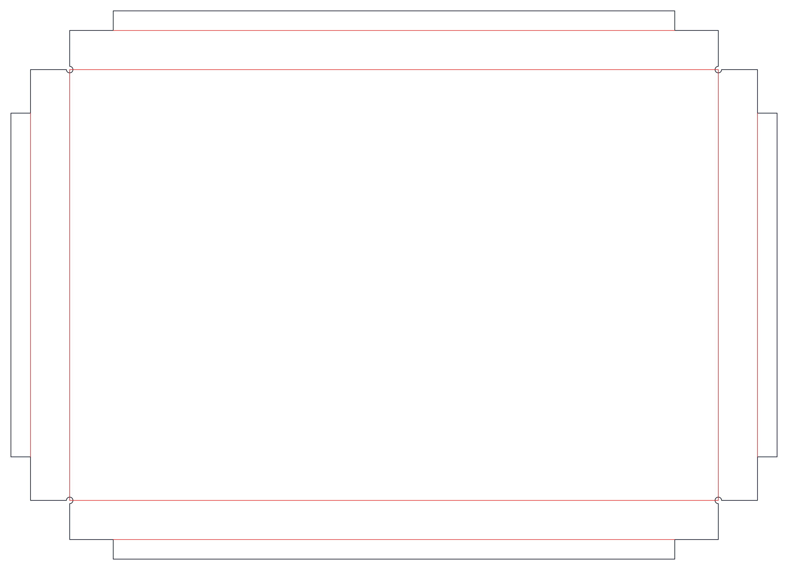
The real developed length of a folded panel is shorter than the sum of its faces. At the fold, the material does not follow the sharp corner of the drawing: it turns around the residual skin and “consumes” less than the two outer dimensions. The difference, per fold, is the deduction. On the default flat cassette — 600 × 400 mm, returns 40 mm, tabs 20 mm — each direction crosses four folds (two returns, two tabs):
developed = Σ lengths − Σ deductions
          = 600 + 2 · (40 + 20) − 4 · 4 = 704 mm   (width)
= 400 + 2 · (40 + 20) − 4 · 4 = 504 mm (height)The engine splits each deduction in two halves: each face loses r / 2 along the fold edge, then the whole sub-tree of the child face is translated by −r towards the parent so the two trimmed edges meet on one junction line. The groove axis ends up r / 2 on the parent side, where the two edges touch. This is why a drilling margin must cover half the deduction: the fold axis moves into the face.
Why “deduction = thickness” is only a default
The deduction depends on the machine, the material and the groove depth — hence on the cutter angle, the residual skin and the sheet batch. The engine does not hard-code it: it reads it from the material profile. When the table is empty it falls back to deduction = thickness (4 mm for ACM 4 mm) and writes it on every part: DEDUCTION_UNCALIBRATED, “run the calibration wizard before a batch”. The cut sheet carries the note “deduction NOT calibrated”.
That default is an order of magnitude, not a measurement. On a cassette with four folds per direction, a 0.5 mm error per fold makes 2 mm on the finished dimension: enough for a 10 mm façade joint to become 8 or 12.
The test-piece method
The calibration coupon is a U-shaped test piece: a 60 mm wide strip, 2 folds at the same apex angle θ, three faces of nominal length L = 80 mm. It is cut with the assumed deduction r0 of the current profile, frozen at download time; a U<angle> mark is engraved on the REPERE layer to recognise it once folded.
- Pick the cutter in the studio wizard — cutters used by the open family and not yet calibrated are flagged — and download the test piece.
- Machine the piece and fold both folds into a U.
- Measure with a caliper only the middle face, on the outside, from one fold to the other.
- Type the measurement: the wizard states the gap plainly (“folds 0.4 mm longer than planned”) and records it as a calibration point of the material profile, replacing the point at the same angle.
middle face after folding = L − r0 + r
r = r0 + (measured − L)

example: L = 80 mm, r0 = 4 mm, measured = 79.3 mm → r = 4 + (79.3 − 80) = 3.3 mm

general method, k folds, sum of the k + 1 faces:
r = r0 + (measured − (k + 1) · L) / k
Each fold gives its deduction back equally to the two faces it joins: the V-groove is symmetric, and the engine trims r0/2 on each side when cutting. The middle face of a U touches two folds, so it carries a whole deduction: one measurement is enough, with no addition or division. One measurement, one unknown, exact in one step — which is why there is still one test piece per cutter angle.
How the table is read
Each calibration point carries an apex angle, a deduction and a date. Between two points the engine interpolates linearly. Above the largest calibrated angle it clamps to the last point. Below the smallest, it goes down towards (0°, 0 mm): a fold of zero angle consumes nothing, and clamping to the smallest point would give a 10° fold the deduction of a 45° fold.
| Apex angle | Empty table | Table: 90° → 3.3 mm | Table: 45° → 1.8 mm, 90° → 3.3 mm |
|---|---|---|---|
| 20° | 4 mm (default) | 0.73 mm (towards 0°) | 0.80 mm (towards 0°) |
| 45° | 4 mm (default) | 1.65 mm (towards 0°) | 1.80 mm (point) |
| 90° | 4 mm (default) | 3.30 mm (point) | 3.30 mm (point) |
| 120° | 4 mm (default) | 3.30 mm (clamped) | 3.30 mm (clamped) |
The two cases where the deduction is not applied
- Cyclic pattern (continuous sheet, origami, closing folds): no sub-tree can be shifted without breaking the cycle. The pattern is machined at design size and
DEDUCTION_SKIPPED_CYCLICstates how much the finished part will shrink per fold. - Apex folds of a relief cassette: the fan of facets around a vertex would each shift in its own direction. These folds are a few degrees, their deduction is under a millimetre:
DEDUCTION_SKIPPED_APEX. Returns and tabs keep their full deduction.
What the deduction changes elsewhere
The corner relief radius is max(tool radius, r / 2 + clearance): max(3; 2 + 0.5) = 3 mm with the Ø 6 mm contour tool, the default deduction and the 0.5 mm clearance. A return must exceed groove width + r / 2 = 7.2 + 2 = 9.2 mm on 4 mm, otherwise GROOVE_TOO_DEEP. A drilling margin must cover r / 2 + half groove + 1 mm, otherwise DRILL_IN_GROOVE. See returns, tabs and corner reliefs and V-groove.
Read next: the coupon calibration, step by step.
Frequently asked questions
- What bend deduction for 4 mm Alucobond?
- The one you measure. The generator starts from deduction = thickness (4 mm) for lack of calibration, and replaces that value with the coupon-measured point for each cutter angle. Between two calibrated angles it interpolates linearly; below the smallest angle it goes down towards (0°, 0 mm).
- Why one coupon per angle?
- One measurement, one unknown: exact in one step. Three angles on the same coupon would give one measurement for three unknowns, unsolvable.
- Does the deduction show in the 3D view?
- No. The 3D view shows the design intent at finished dimensions. The deduction only exists in the manufacturing pattern: the DXF, the flat view and the cut sheet.
- What happens if the deduction makes a face disappear?
- The engine emits FEATURE_DROPPED naming the fold and the face, including when the deduction strip opens an interior cut-out onto the edge. Nothing is dropped silently.